5.4.4 Securing the Base Unit using the mounting plate

About the mounting plate

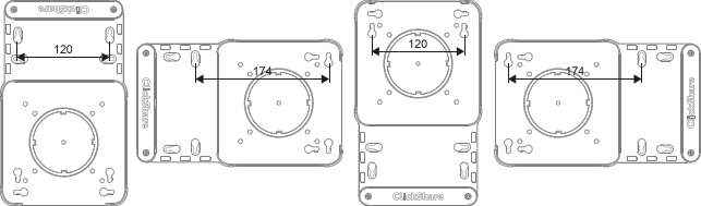
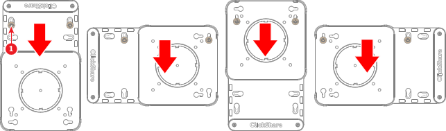
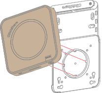
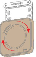
The mounting plate is an optional accessory. It holds both the Base Unit and its connected wiring in place. The mounting plate can be oriented in the four cardinal directions depending on which pair of key holes is chosen. Each orientation follows the same general procedure.
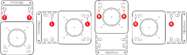
Image 5–34
T
Top orientation screw holes
L
Left orientation screw holes
B
Bottom orientation screw holes
R
Right orientation screw holes
About install locations

The Base Unit can be installed using the mounting base to the following options:

Tip: The Base Unit weighs: 720 g.
Required parts
How to install
  1. Will the mounting plate be installed horizontally or vertically?

    • If horizontally, foresee two holes spaced 174 mm apart.
    • If vertically, foresee two holes spaced 120 mm apart.
    Image 5–35
  2. Insert two M4 screws, each at least 25.4 mm long, into the prepared holes.
  3. Slide the chosen keys of the mounting plate over the two prepared screws (reference 1) to lock the keys.

    Tip: Tighten the prepared screws if easy access to the mounting plate is not needed.
    Image 5–36
  4. Secure the mounting plate with additional screws if needed. (optional)
  5. Position the grooves on the bottom of the Base Unit on the mounting plate as illustrated.

    Note: Ensure the ports on the back of the Base Unit are facing the extension of the mounting plate.
    Image 5–37
  6. Rotate the Base Unit clockwise.

    Image 5–38
  7. Secure the cables to the mounting plate. For more information, see “Securing the cables in the mounting plate”.