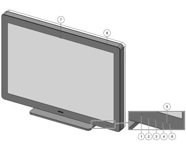
1.2 At a glance

Front view
Image 1–1
  1. Front key 1
  2. Front key 2
  3. Front key 3
  4. Front key 4
  5. Orange power LED (for an overview of the different power LED states, see “Power LED”)
  6. White power LED (for an overview of the different power LED states, see “Power LED”)
  7. I-Guard sensor
  8. Ambient light sensor
Rear view
Image 1–2
  1. Connector cover
  2. Tilt lock pin (only for transportation)
  3. Tilt & swivel foot
  4. Cable duct
  5. Foot lock pin (only for transportation)
  6. SoftGlow Task light
  7. SoftGlow Wall light
Note: Store the foot lock pin and tilt lock pin for possible future transportation of the display.
Connectors

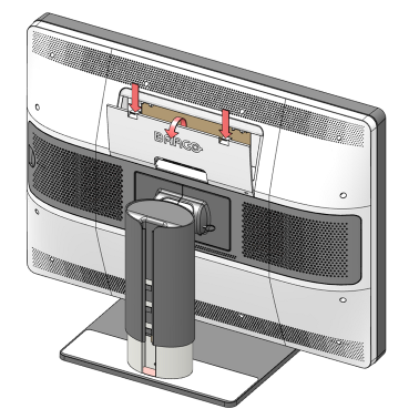
To access the rear connectors, gently push the two lips on the top of the cover then pull the top of the cover away from the display and remove it.

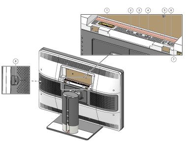
Following connectors are available:

Image 1–3
  1. Power input
  2. DisplayPort input
  3. DisplayPort input
  4. Not used
  5. USB-A upstream connector
  6. USB-B downstream connector
  7. USB-B downstream connector
  8. USB-B downstream connector
Film clip

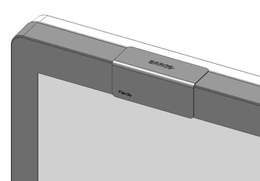
The film clip can be used to hold a radiological film when using the I-Luminate function as a light box. See “I-Luminate” and “I-Luminate default mode”.

Image 1–4
Barco Touchpad

The Barco Touchpad can control Barco’s Intuitive Workflow Tools and allows you to control diagnostic imaging and other viewing applications with configurable multi-touch gestures and touchpad function activation buttons. Using and configuring the Barco Touchpad requires Barco’s MXRT display controller and driver to be installed on your workstation.

For more information and installation instructions, please check the Barco “Display Controller and Intuitive Workflow Tools” user guide on the included documentation CD, or at www.barco.com/support.